In this week’s blog we’re taking a look at Fan Laws; the fundamentals when it comes to selecting fan size and power.

Fan Laws are used to determine theoretical performance data for varying combinations of impeller speed, diameter and air densities. Here we will only consider the relationship and effect of speed on volume, pressure and power for a constant impeller diameter handling air at a constant density:
When speed is varied on the same size, handling constant density air (e.g. fan used with frequency inverter drive)
Flow Rate varies directly as the speed. Q2 m³/s = (rpm2/rpm1) x Q1 m³/s
Pressure varies as the square of the speed. P2 Pa = (rpm2/rpm1)² x P1 Pa
Power varies as the Cube of speed.
Power2 kW= (rpm2/rpm1)³ x Power1 kW
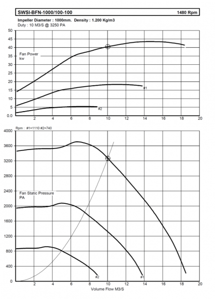
?Performance Curve Showing Speed Variation
 The above graph shows the performance curve and speed variation where the maximum speed is 1480 RPM and the reduced speeds are 1110 RPM (75%) and 740 RPM (50%) respectively.
Below we will only consider the relationship and effect of fan diameter on volume, pressure and power for a constant impeller speed handling air at a constant density:
Flow Rate varies as the cube of the diameter. Q2 m³ /s = (D2/D1)³ x Q1 m³ /s
Pressure varies as the square of the diameter. P2 Pa = (D2/D1)² x P1 Pa
Power varies as the fifth power of the diameter
Power2 kW= (rpm2/rpm1)5 x Power1 kW
Pressure & Power vary directly proportional to gas density, combining speed, diameter & density we have the following :-
Q2 = Q1 x (n2/n1) x (D2/D1)3
P2 = P1 x (n2/n1)2 x (D2/D1)2 x (?2/ ?1) W2 = W1 x (n2/n1)3 x (D2/D1)5 x (?2/ ?1)
Where
Q = flow rate
P = pressure (total, static, or dynamic) ? = gas density
n = fan rotational speed
D = impeller diameter
W = impeller power


